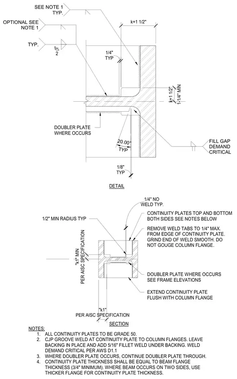
Grade 50 steel continuity plates and optional doubler plates install at steel column flanges. Complete joint penetration groove welds attach the continuity plates to the column flanges, leaving the backing in place with an additional five-sixteenths inch fillet weld underneath per AWS D1.1 demand critical standards. Continuity plates are detailed to match the beam flange thickness with a minimum three-quarter inch thickness and extend flush with the column flange edges. Weld tabs are required to be removed to one-quarter inch maximum from the plate edge with smooth ground ends, taking care to avoid gouging the column flange.
1/2" MIN RADIUS TYP EXTEND CONTINUITY PLATE FLUSH WITH COLUMN FLANGE REMOVE WELD TABS TO 1/4" MAX. FROM EDGE OF CONTINUITY PLATE. GRIND END OF WELD SMOOTH. DO NOT GOUGE COLUMN FLANGE. NOTES: 1. ALL CONTINUITY PLATES TO BE GRADE 50. 2. CJP GROOVE WELD AT CONTINUITY PLATE TO COLUMN FLANGES. LEAVE BACKING IN PLACE AND ADD 5/16" FILLET WELD UNDER BACKING. WELD DEMAND CRITICAL PER AWS D1.1 3. WHERE DOUBLER PLATE OCCURS, CONTINUE DOUBLER PLATE THROUGH. 4. CONTINUITY PLATE THICKNESS SHALL BE EQUAL TO BEAM FLANGE THICKNESS (3/4" MINIMUM). WHERE BEAM OCCURS ON TWO SIDES, USE THICKER FLANGE FOR CONTINUITY PLATE THICKNESS. DOUBLER PLATE WHERE OCCURS SEE FRAME ELEVATIONS CONTINUITY PLATES TOP AND BOTTOM BOTH SIDES SEE NOTES BELOW WELD TYP. 1/4'' NO "k1" MIN PER AISC SPECIFICATION "k1" PER AISC SPECIFICATION 1/8" TYP TYP 20.00° k+1 1/2" 1-1/4'' MIN k+1 1/2" 1/4" TYP TYP. SEE NOTE 1 TYP. FILL GAP DEMAND CRITICAL DOUBLER PLATE WHERE OCCURS DETAIL SECTION t PL 2 OPTIONAL SEE NOTE 1
Members view this detail in full resolution, download the CAD files (SVG, PDF), and can adapt it in the built-in CAD editor — export DXF, DWG, or PDF.
Start membership