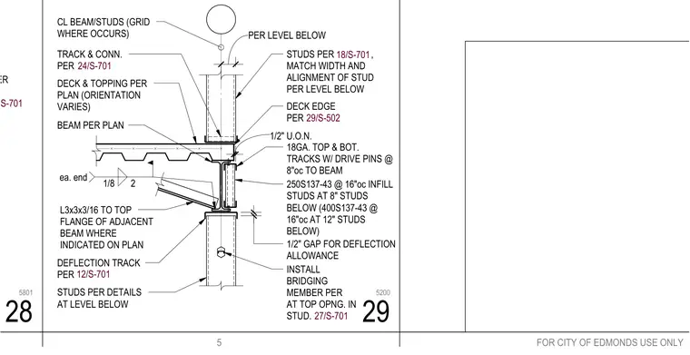
Cold-formed steel framing at a floor deck edge incorporates a half-inch gap for deflection allowance under the structural beam. Infill studs measuring 250S137-43 at sixteen inches on center are paired with eighteen-gauge top and bottom tracks secured to the beam using drive pins at eight inches on center. An L3x3x3/16 angle is welded to the top flange of the adjacent beam with two-inch welds at each end. A bridging member is installed at the top opening of the stud. The assembly accommodates vertical movement between the floor slab and exterior or interior wall framing.
MASONRY VENEER 6/S-701 INSTALL BRIDGING MEMBER PER AT TOP OPNG. IN STUD. DEFLECTION TRACK PER 1/2" GAP FOR DEFLECTION ALLOWANCE TRACK & CONN. PER DECK EDGE PER DECK & TOPPING PER PLAN (ORIENTATION VARIES) STUDS PER , MATCH WIDTH AND ALIGNMENT OF STUD PER LEVEL BELOW BEAM PER PLAN STUDS PER DETAILS AT LEVEL BELOW PER LEVEL BELOW 1/2" U.O.N. CL BEAM/STUDS (GRID WHERE OCCURS) 24/S-701 18/S-701 27/S-701 29/S-502 12/S-701 L3x3x3/16 TO TOP FLANGE OF ADJACENT BEAM WHERE INDICATED ON PLAN 1/8 2 ea. end 250S137-43 @ 16"oc INFILL STUDS AT 8" STUDS BELOW (400S137-43 @ 16"oc AT 12" STUDS BELOW) 18GA. TOP & BOT. TRACKS W/ DRIVE PINS @ 8"oc TO BEAM 5 FOR CITY OF EDMONDS USE ONLY 28 5801 29 5200
Members view this detail in full resolution, download the CAD files (SVG, PDF), and can adapt it in the built-in CAD editor — export DXF, DWG, or PDF.
Start membership