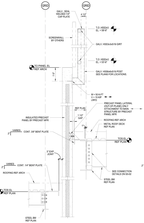
An insulated precast concrete wall panel connects to a structural steel framing system at a roof level, featuring a galvanized HSS6x6x5/16 post and HSS3x3x5/16 girts supporting a screenwall above. The precast panel incorporates a lateral out-of-plane attachment to the main structure with continuous three-eighths-inch and one-quarter-inch bent plates, maintaining a one-and-a-half-inch gap. The roof assembly includes a metal deck bearing on a structural steel beam, with connection details referenced on sheet S5-02. The top of the HSS girt reaches elevations of fifty-nine feet six inches and fifty-three feet six inches, with design loads indicated as a moment of fifty kip-feet and shear of fifteen kips under LRFD. A seal-welded one-quarter-inch cap plate is provided at the top of the steel assembly.
GRID GRID 2" TOS EL REF PLAN STEEL BM REF PLAN METAL ROOF DECK REF PLAN REF PLAN ROOFING REF ARCH 1" TO PANEL EL REF ARCH INSULATED PRECAST PANEL BY PRECAST MFR GAP 1 1/2" TOS EL REF PLAN STEEL BM REF PLAN T.O. HSS3x3 EL. = 59'-6" T.O. HSS3x3 EL. = 53'-6" GALV. HSS3x3x5/16 GIRT GALV. HSS6x6x5/16 POST SEE PLANS FOR LOCATIONS. 1'-0" GALV., SEAL WELDED 1/4" CAP PLATE SCREENWALL BY OTHERS M = 50 K-FT V = 15 KIP LRFD 4 1/2" SEE CONNECTION DETAILS ON S5-02 JOINT 3" EXP. ROOFING REF ARCH PRECAST PANEL LATERAL (OUT-OF-PLANE) ONLY ATTACHMENT TO MAIN STRUCTURE BY PRECAST PANEL MFR CONT. 3/8" BENT PLATE VARIES 2" CONT. 1/4" BENT PLATE VARIES 2"
Members view this detail in full resolution, download the CAD files (SVG, PDF), and can adapt it in the built-in CAD editor — export DXF, DWG, or PDF.
Start membership