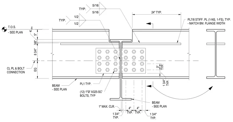
Two aligned structural steel beams connect end-to-end with a one-inch maximum clearance, joined by center-line connection plates and twelve one-inch diameter A325-SC high-strength bolts typical per side. Seven-eighths-inch thick stiffener plates matching the beam flange width are welded to the top and bottom flanges with five-sixteenths-inch and one-half-inch fillet welds extending twenty-four inches typically. The top of steel is positioned as sized per plan with specific dimensional clearances for the web and flange configurations.
EQ 8 3/4" 3/8" K 5" des 24" TYP. 1" MAX. CLR. TYP. 1 3/4" TYP. 4" TYP. 4" TYP. 1 3/4" TYP. 1 3/4" TYP. 3" BEAM - SEE PLAN BEAM - SEE PLAN (12) 1"Ø 'A325-SC' BOLTS, TYP CL PL & BOLT CONNECTION PL1 TYP. PL7/8 STIFF. PL (1-NS, 1-FS), TYP. - MATCH BM. FLANGE WIDTH 1/2 1/2 TYP. 5/16 5/16 TYP. T.O.S. - SEE PLAN
Members view this detail in full resolution, download the CAD files (SVG, PDF), and can adapt it in the built-in CAD editor — export DXF, DWG, or PDF.
Start membership