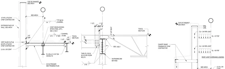
Roof joist overhang loading and parapet framing connections comprise an in-framing beam connected via a three-eighths-inch through plate with six three-quarter-inch diameter A325N bolts, complemented by five-sixteenths-inch fillet welds. Continuous HSS blocking spans between the steel joists, supported by channel members connected with three-sixteenths-inch welds and a three-eighths-inch plate with one three-quarter-inch diameter high-strength bolt. A continuous L5x5x3/8 angle supports the cold-formed metal framing, utilizing vertical slide clips at each metal stud. Dead and snow load parameters of thirty-seven PSF and ninety PSF respectively are applied across the roof joist overhang.
CANOPY BAND FRAMING BY CFMF CONTRACTOR SEE ARCH SL = 90 PSF DL = 37 PSF SL = 2K PER JOIST DL = 2K PER JOIST ROOF JOIST OVERHANG LOADING TOP OF PARAPET SEE ARCH L5 x5 x 3/8 2 1/2" 1 1/2" 3" 1 1/2" 3" 5" JST SEAT 1 1/2" 3" 1/2" THRU PL 3/8 W/ (6) 3/4 DIA A325N BOLTS IN-FRAMING BM BEYOND 5/16 3/S5.1 SEE TOS EL SEE PLAN VERT SLIDE CLIP @ EA MTL STUD BY CFMF CONTRACTOR C5 OUTRIGGER SEE FRAMING PLAN 1/4 TYP @ EA CHANNEL L5 x5 x 3/8 CONT 12" MTL STUD BY CFMF CONTRACTOR TOP OF PARAPET SEE ARCH 3/16 4" MIN CHANNEL TO BM 1" PL 3/8 w/ (1) 3/4" DIA HS BOLTS EXTERIOR FACE OF WALL, SEE ARCH TOS EL SEE PLAN 1 1/2" GAP 1/2" GAP 1/2" SEE ARCH CONT HSS BLOCKING BTWN STEEL JST's. SEE 21/S5.1
Members view this detail in full resolution, download the CAD files (SVG, PDF), and can adapt it in the built-in CAD editor — export DXF, DWG, or PDF.
Start membership