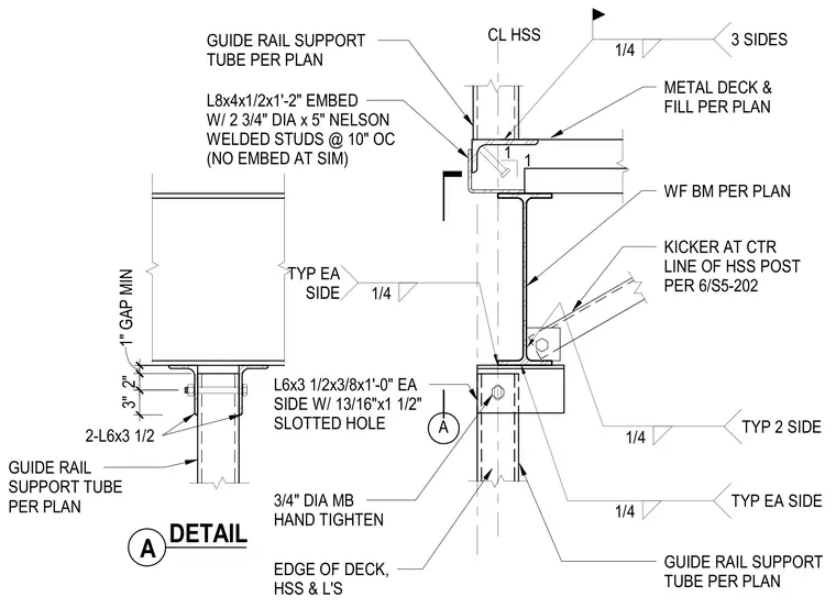
Structural connection for an elevator guide rail support tube framing into a wide flange beam and concrete-filled metal deck. The assembly features an L8x4x1/2 by 1 foot 2 inch embed angle with two 3/4 inch diameter by 5 inch Nelson welded studs at 10 inches on center. A guide rail support tube connects below using an L6x3-1/2x3/8 by 1 foot 0 inch angle on each side, detailed with 13/16 by 1-1/2 inch slotted holes and 3/4 inch diameter machine bolts hand tightened to allow movement. Additional lateral stability is provided by a kicker at the centerline of the hollow structural section post, welded with quarter-inch fillets typical on two sides. A one-inch minimum gap is maintained at the support interface.
A 1 1 L8x4x1/2x1'-2" EMBED W/ 2 3/4" DIA x 5" NELSON WELDED STUDS @ 10" OC (NO EMBED AT SIM) WF BM PER PLAN L6x3 1/2x3/8x1'-0" EA SIDE W/ 13/16"x1 1/2" SLOTTED HOLE 3/4" DIA MB HAND TIGHTEN GUIDE RAIL SUPPORT TUBE PER PLAN CL HSS METAL DECK & FILL PER PLAN GUIDE RAIL SUPPORT TUBE PER PLAN KICKER AT CTR LINE OF HSS POST PER 6/S5-202 1/4 TYP EA SIDE 1/4 TYP EA SIDE 1/4 TYP 2 SIDE 1/4 3 SIDES EDGE OF DECK, HSS & L'S GUIDE RAIL SUPPORT TUBE PER PLAN 2-L6x3 1/2 3" 2" 1" GAP MIN A DETAIL
Members view this detail in full resolution, download the CAD files (SVG, PDF), and can adapt it in the built-in CAD editor — export DXF, DWG, or PDF.
Start membership