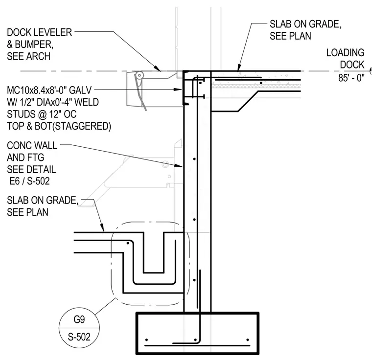
A reinforced concrete wall and footing support a concrete slab on grade at the loading dock elevation of eighty-five feet and zero inches. An MC10x8.4 galvanized steel channel measuring eight feet zero inches long is embedded at the top of the concrete wall with one-half inch diameter by four-inch long weld studs spaced at twelve inches on center, arranged top and bottom staggered. A dock leveler and bumper assembly coordinates with the architectural layout at the dock edge. The foundation wall details interface with adjacent slabs on grade per the structural plans.
LOADING DOCK 85' - 0" CONC WALL AND FTG SEE DETAIL SLAB ON GRADE, SEE PLAN SLAB ON GRADE, SEE PLAN S-502 G9 / E6 S-502 DOCK LEVELER & BUMPER, SEE ARCH MC10x8.4x8'-0" GALV W/ 1/2" DIAx0'-4" WELD STUDS @ 12" OC TOP & BOT(STAGGERED)
Members view this detail in full resolution, download the CAD files (SVG, PDF), and can adapt it in the built-in CAD editor — export DXF, DWG, or PDF.
Start membership