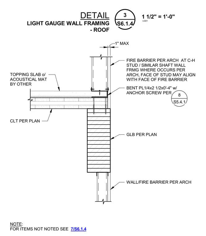
A cold-formed steel light gauge wall framing assembly sits atop a cross-laminated timber floor with a topping slab over an acoustical mat. A bent plate measuring 1/4 inch by 2-1/2 inches by 4 inches connects the framing using anchor screws specified per detail S5.4.1. A fire barrier per architectural requirements occurs at the C-H stud and shaft wall framing, maintaining a 1-inch maximum clearance. A glued-laminated timber beam supports the floor assembly from below.
CLT PER PLAN 1" MAX FIRE BARRIER PER ARCH AT C-H STUD / SIMILAR SHAFT WALL FRMG WHERE OCCURS PER ARCH, FACE OF STUD MAY ALIGN WITH FACE OF FIRE BARRIER WALL/FIRE BARRIER PER ARCH GLB PER PLAN TOPPING SLAB o/ ACOUSTICAL MAT BY OTHER BENT PL1/4x2 1/2x0'-4" w/ ANCHOR SCREW PER 8 S5.4.1 NOTE: FOR ITEMS NOT NOTED SEE 7/S6.1.4 DETAIL S6.1.4 1 1/2" = 1'-0" 3 LIGHT GAUGE WALL FRAMING - ROOF LGD1
Members view this detail in full resolution, download the CAD files (SVG, PDF), and can adapt it in the built-in CAD editor — export DXF, DWG, or PDF.
Start membership