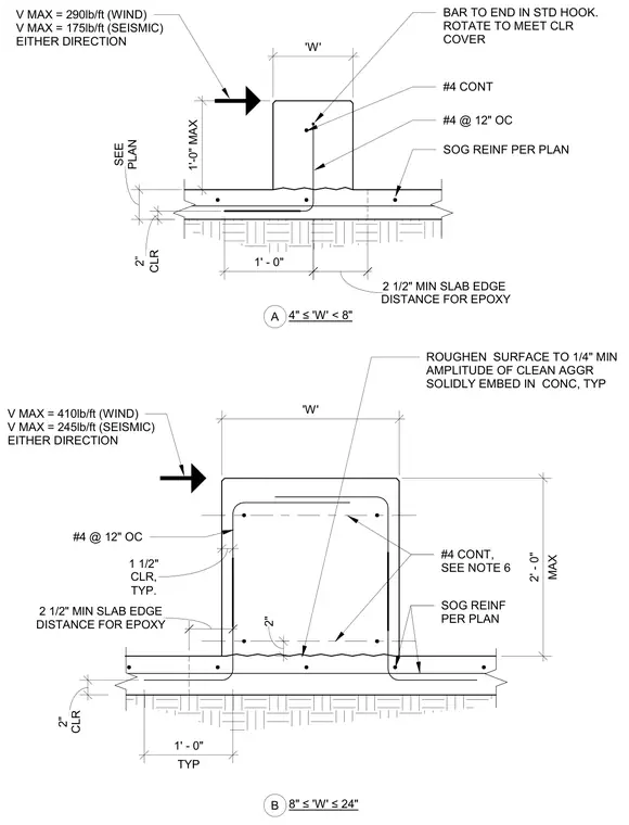
Concrete curbs are cast monolithically with or anchored to a slab on grade, featuring varying widths designated as "W". Reinforcement consists of continuous number four bars and number four bars spaced at twelve inches on center, with specific clearances and standard hook terminations. The concrete surface at the slab interface requires roughening to a quarter-inch minimum amplitude of clean aggregate. Shear capacity limits are provided for wind and seismic loading in either direction based on the curb width category. Minimum slab edge distances for epoxy anchorage and maximum dimensions are explicitly detailed for each configuration.
PLAN SEE CLR 2 ” SOG REINF PER PLAN #4 CONT 'W' 1'-0" MAX 1' - 0" TYP. 1 1/2" CLR, MAX 2' - 0" 2" #4 CONT, SEE NOTE 6 TYP 1' - 0" CLR 2" #4 @ 12" OC A 4" ≤'W' < 8" B 8" ≤'W' ≤24" #4 @ 12" OC SOG REINF PER PLAN 'W' ROUGHEN SURFACE TO 1/4" MIN AMPLITUDE OF CLEAN AGGR SOLIDLY EMBED IN CONC, TYP V MAX = 290lb/ft (WIND) V MAX = 175lb/ft (SEISMIC) EITHER DIRECTION V MAX = 410lb/ft (WIND) V MAX = 245lb/ft (SEISMIC) EITHER DIRECTION BAR TO END IN STD HOOK. ROTATE TO MEET CLR COVER DISTANCE FOR EPOXY 2 1/2" MIN SLAB EDGE DISTANCE FOR EPOXY 2 1/2" MIN SLAB EDGE
Members view this detail in full resolution, download the CAD files (SVG, PDF), and can adapt it in the built-in CAD editor — export DXF, DWG, or PDF.
Start membership