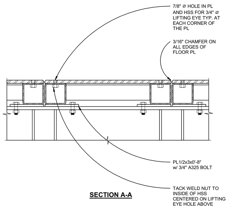
A structural steel floor assembly features hollow structural section members tied together by a half-inch by three-inch by zero-foot-eight-inch plate secured with a three-quarter-inch A325 bolt. A seven-eighths-inch diameter hole is drilled through both the plate and the hollow structural section to accommodate a three-quarter-inch diameter lifting eye located at each corner of the plate. A nut is tack-welded to the inside of the hollow structural section, centered directly below the lifting eye hole. All edges of the floor plate feature a three-sixteenths-inch chamfer.
7/8" ⌀ HOLE IN PL AND HSS FOR 3/4" ⌀ LIFTING EYE TYP. AT EACH CORNER OF THE PL 3/16" CHAMFER ON ALL EDGES OF FLOOR PL PL1/2x3x0'-8" w/ 3/4" A325 BOLT TACK WELD NUT TO INSIDE OF HSS CENTERED ON LIFTING EYE HOLE ABOVE SECTION A-A
Members view this detail in full resolution, download the CAD files (SVG, PDF), and can adapt it in the built-in CAD editor — export DXF, DWG, or PDF.
Start membership