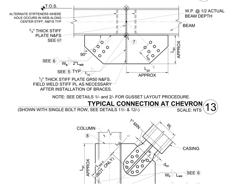
A chevron brace connection frames into a continuous steel beam and column. A gusset plate is bolted to the brace member and welded to the supporting members, incorporating three-quarter-inch and half-inch Grade 50 stiffener plates on near and far sides as indicated. Field welds are specified to be completed as necessary after the installation of the braces. Alternate stiffeners are detailed where holes occur in the web along the center stiffener.
4 COLUMN 8 e L bh L wp-h (BOT. ONLY) CASING 1" MIN W L TYPICAL CONNECTION AT CHEVRON SCALE: NTS 13 L gc APPROX 6 SEE W c L wc (SHOWN WITH SINGLE BOLT ROW, SEE DETAILS 11/- & 12/-) d bh L gc APPROX 3 4 " THICK STIFF PLATE N&FS TYP 5 SEE W.P. @ 1/2 ACTUAL BEAM DEPTH X X 90° 516 12 " THICK STIFF PLATE GR50 N&FS. 7 L gb APPROX W b 6 SEE 2*L wb BEAM T.O.S. L bh G7 SEE FIELD WELD STIFF PL AS NECESSARY AFTER INSTALLATION OF BRACES. NOTE: SEE DETAILS 1/- and 2/- FOR GUSSET LAYOUT PROCEDURE. ALTERNATE STIFFENERS WHERE HOLE OCCURS IN WEB ALONG CENTER STIFF, N&F/S TYP
Members view this detail in full resolution, download the CAD files (SVG, PDF), and can adapt it in the built-in CAD editor — export DXF, DWG, or PDF.
Start membership