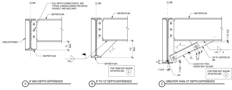
Three structural steel beam connection details show framing conditions for beams with varying depth offsets at supporting columns or girders. The first detail accommodates a maximum six-inch depth difference using a full-depth connection plate and web stiffeners on the supporting member. The second detail handles six to twelve-inch depth differences with a gusset plate welded beneath the supported beam flange. The third detail addresses depth differences greater than twelve inches using an L4x4x1/4 angle brace fastened with one-inch diameter A325SC bolts at each end and a three-eighths-inch center plate.
MAX 6" BM PER PLAN FULL DEPTH CONNECTION PL, SEE TYPICAL W BEAM CONNECTION DETAIL FOR BOLT AND WELD INFO BM PER PLAN CL BM CL BM 2 1 1 1/2" CLR TYP 2" 1/2" 1" CLR 1" CLR L4x4x1/4 W/ 1"DIA A325SC BOLT EA END 3/8" PL CENTER ON BM WP 1/4 8 6" MAX DEPTH DIFFERENCE A GREATER THAN 12" DEPTH DIFFERENCE C 6" TO 12" DEPTH DIFFERENCE B MAX 1'-0" BM PER PLAN BM PER PLAN CL BM WEB STIFFENER FOR ITEMS NOT SHOWN OR NOTED SEE A 1 1 BM PER PLAN TW 2" FOR ITEMS NOT SHOWN OR NOTED SEE A
Members view this detail in full resolution, download the CAD files (SVG, PDF), and can adapt it in the built-in CAD editor — export DXF, DWG, or PDF.
Start membership