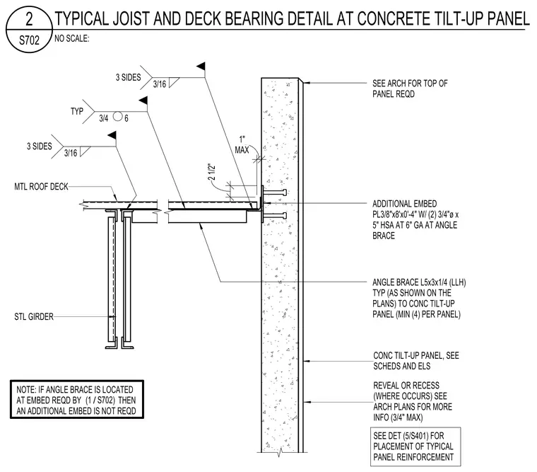
The roof framing bears against a concrete tilt-up wall panel utilizing an angle brace consisting of an L5x3x1/4 member welded with a three-sixteenths fillet weld on three sides. An additional embed plate measuring three-eighths by eight inches by four inches is anchored with two three-quarter-inch diameter by five-inch heavy stud anchors at a six-inch gauge at the angle brace location. A steel girder supports the metal roof deck, which is welded with three-sixteenths fillet welds on three sides. Clearances allow for a one-inch maximum gap and a two-and-a-half-inch maximum dimension, with reveals or recesses permitted up to three-quarters of an inch where required.
SEE ARCH FOR TOP OF PANEL REQD ADDITIONAL EMBED PL3/8"x8'x0'-4" W/ (2) 3/4"ø x 5" HSA AT 6" GA AT ANGLE BRACE 3 SIDES 3/16 NOTE: IF ANGLE BRACE IS LOCATED AT EMBED REQD BY THEN AN ADDITIONAL EMBED IS NOT REQD TYP 3/4 6 ANGLE BRACE L5x3x1/4 (LLH) TYP (AS SHOWN ON THE PLANS) TO CONC TILT-UP PANEL (MIN (4) PER PANEL) 3 SIDES 3/16 STL GIRDER MTL ROOF DECK REVEAL OR RECESS (WHERE OCCURS) SEE ARCH PLANS FOR MORE INFO (3/4" MAX) CONC TILT-UP PANEL, SEE SCHEDS AND ELS 2 1/2" MAX 1" SEE DET (5/S401) FOR PLACEMENT OF TYPICAL PANEL REINFORCEMENT / (1 S702) NO SCALE: S702 2 TYPICAL JOIST AND DECK BEARING DETAIL AT CONCRETE TILT-UP PANEL
Members view this detail in full resolution, download the CAD files (SVG, PDF), and can adapt it in the built-in CAD editor — export DXF, DWG, or PDF.
Start membership