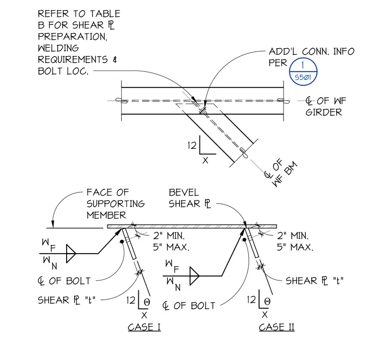
A wide-flange beam frames into a supporting wide-flange girder at an angle. A beveled shear plate of thickness 't' welds to the face of the supporting member. Connection geometry follows a 12-to-X slope, with bolt centerlines positioned between two and five inches from the face of the supporting member. Case I and Case II provide variations for the shear plate orientation relative to the beam web. Refer to detail 1 on sheet S501 for additional connection information; Table B governs shear plate preparation, welding requirements, and bolt locations.
Members view this detail in full resolution, download the CAD files (SVG, PDF), and can adapt it in the built-in CAD editor — export DXF, DWG, or PDF.
Start membership