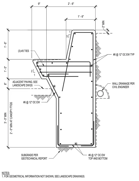
A precast concrete seat wall features an integrated backrest and reinforced concrete stem wall. The assembly is detailed with number six reinforcing bars spaced at twelve inches on center each way throughout the vertical faces, and top and bottom reinforcement in the base. Three number three ties reinforce the seat cantilever. Wall drainage and subgrade requirements are coordinated per civil engineering and geotechnical reports.
2" MIN 1' - 6" 2' - 6" 9" 1 5 1' - 0" 1' - 6" 6" 2' - 0" MIN AT CANOPY FTGS 3' - 0" MIN 1 2 ADJACENT PAVING. SEE LANDSCAPE DWGS SUBGRADE PER GEOTECHNICAL REPORT WALL DRAINAGE PER CIVIL ENGINEER (3)-#3 TIES #6 @ 12" OC EW TYP #6 @ 12" OC EW TOP AND BOTTOM #6 @ 12" OC EW NOTES: 1. FOR GEOMETRICAL INFORMATION NOT SHOWN, SEE LANDSCAPE DRAWINGS.
Members view this detail in full resolution, download the CAD files (SVG, PDF), and can adapt it in the built-in CAD editor — export DXF, DWG, or PDF.
Start membership