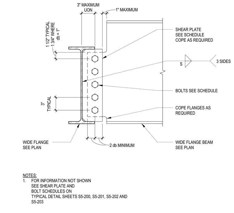
A wide flange beam frames into a supporting wide flange member with coped top and bottom flanges to clear the connection. A shear plate is welded to the support on three sides with fillet welds and bolted to the supported beam web. Bolt sizes, spacings, and edge distances follow standard structural criteria, including a one-inch maximum distance from the cope to the face of the support and a two-bolt-diameter minimum edge distance. Additional sizing and fastener schedules are referenced on typical detail sheets.
WIDE FLANGE BEAM SEE PLAN COPE FLANGES AS REQUIRED BOLTS SEE SCHEDULE SHEAR PLATE SEE SCHEDULE COPE AS REQUIRED WIDE FLANGE SEE PLAN 1" MAXIMUM db = 1" 1 1/2" TYPICAL 1 3/4" WHERE TYPICAL 3" 2 db MINIMUM 3" MAXIMUM UON S 3 SIDES NOTES: 1. FOR INFORMATION NOT SHOWN SEE SHEAR PLATE AND BOLT SCHEDULES ON TYPICAL DETAIL SHEETS S5-200, S5-201, S5-202 AND S5-203
Members view this detail in full resolution, download the CAD files (SVG, PDF), and can adapt it in the built-in CAD editor — export DXF, DWG, or PDF.
Start membership