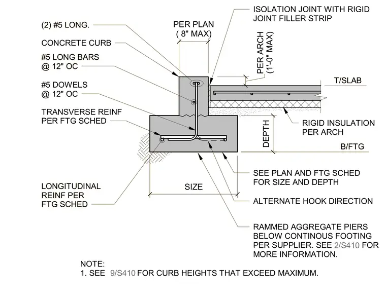
A continuous concrete footing supports a concrete curb and adjacent concrete slab-on-grade. The footing features transverse and longitudinal reinforcing bars sized per the footing schedule, with #5 dowels spaced at twelve inches on center tying into the curb above. The concrete curb includes two #5 longitudinal reinforcing bars and is separated from the adjacent slab by an isolation joint with a rigid joint filler strip. Rigid insulation is placed beneath the slab according to architectural specifications, and rammed aggregate piers are installed below the continuous footing per the supplier requirements. Size, depth, and reinforcing details are coordinated with the structural plans and footing schedule.
B/FTG T/SLAB SEE PLAN AND FTG SCHED FOR SIZE AND DEPTH ALTERNATE HOOK DIRECTION DEPTH SIZE #5 DOWELS @ 12" OC LONGITUDINAL REINF PER FTG SCHED TRANSVERSE REINF PER FTG SCHED RAMMED AGGREGATE PIERS BELOW CONTINOUS FOOTING PER SUPPLIER. SEE 2/S410 FOR MORE INFORMATION. (1'-0" MAX) PER ARCH ISOLATION JOINT WITH RIGID JOINT FILLER STRIP CONCRETE CURB (2) #5 LONG. #5 LONG BARS @ 12" OC 2/S410 RIGID INSULATION PER ARCH PER PLAN ( 8" MAX) NOTE: 1. SEE FOR CURB HEIGHTS THAT EXCEED MAXIMUM. 9/S410 B/FTG T/SLAB SEE PLAN AND FTG SCHED FOR SIZE AND DEPTH ALTERNATE HOOK DIRECTION DEPTH SIZE #5 DOWELS @ 12" OC LONGITUDINAL REINF PER FTG SCHED TRANSVERSE REINF PER FTG SCHED RAMMED AGGREGATE PIERS BELOW CONTINOUS FOOTING PER SUPPLIER. SEE 2/S410 FOR MORE INFORMATION. (1'-0" MAX) PER ARCH ISOLATION JOINT WITH RIGID JOINT FILLER STRIP CONCRETE CURB (2) #5 LONG. #5 LONG BARS @ 12" OC 2/S410 RIGID INSULATION PER ARCH PER PLAN ( 8" MAX) NOTE: 1. SEE FOR CURB HEIGHTS THAT EXCEED MAXIMUM. 9/S410
Members view this detail in full resolution, download the CAD files (SVG, PDF), and can adapt it in the built-in CAD editor — export DXF, DWG, or PDF.
Start membership