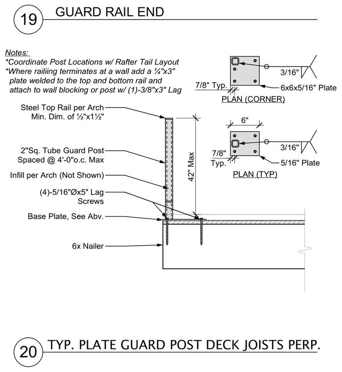
A two-inch square tube steel guard post stands at a maximum height of forty-two inches and fastens to a base plate anchored into a six-inch wood nailer. The assembly uses four five-sixteenth-inch diameter by five-inch lag screws through the base plate into the wood framing. Plan views detail standard and corner base plate configurations measuring six by six inches with three-sixteenth-inch and five-sixteenth-inch plate thicknesses. Post locations coordinate with the rafter tail layout, and terminating conditions at walls require a quarter-inch by three-inch plate welded to the rails and attached with a three-eighth-inch by three-inch lag screw.
19 20 GUARD RAIL END TYP. PLATE GUARD POST DECK JOISTS PERP. 2"Sq. Tube Guard Post Spaced @ 4'-0"o.c. Max 42" Max Steel Top Rail per Arch Min. Dim. of ½"x1½" Base Plate, See Abv. 6x Nailer Infill per Arch (Not Shown) (4)-5/16"Øx5" Lag Screws Notes: *Coordinate Post Locations w/ Rafter Tail Layout *Where railiing terminates at a wall add a ¼"x3" plate welded to the top and bottom rail and attach to wall blocking or post w/ (1)-3/8"x3" Lag 6" 7/8" Typ. PLAN (TYP) 3/16" 5/16" Plate 7/8" Typ. PLAN (CORNER) 3/16" 6x6x5/16" Plate
Members view this detail in full resolution, download the CAD files (SVG, PDF), and can adapt it in the built-in CAD editor — export DXF, DWG, or PDF.
Start membership