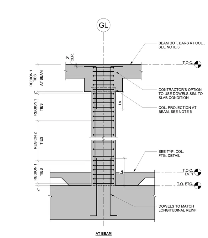
Typical reinforcement configuration for a reinforced concrete column between a foundation and a beam connection. Longitudinal reinforcement extends through the column, tied into the footing with standard hooks and spliced with development length Ls at the base and beam interface. Transverse ties are spaced in distinct zones, featuring region 1 spacing near the beam and footing joints and region 2 spacing through the mid-height of the column. Additional callouts indicate beam bottom bars, column projection dimensions, and contractor options for dowel placement at the slab and beam junctions.
T.O. FTG. T.O.C. LV. 1 DOWELS TO MATCH LONGITUDINAL REINF. T.O.C. 2" TIES REGION 1 TIES REGION 2 TIES REGION 1 2" AT BEAM REGION 1 TIES SEE TYP. COL. FTG. DETAIL Ls COL. PROJECTION AT BEAM, SEE NOTE 5 BEAM BOT. BARS AT COL., SEE NOTE 6 GL AT BEAM CONTRACTOR'S OPTION TO USE DOWELS SIM. TO SLAB CONDITION CLR. 2" Ls
Members view this detail in full resolution, download the CAD files (SVG, PDF), and can adapt it in the built-in CAD editor — export DXF, DWG, or PDF.
Start membership