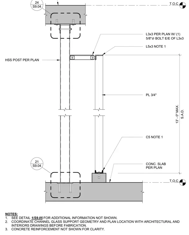
An HSS post spans from the structural concrete slab per plan to the overhead concrete structure, anchored with base plates and post connections detailed in referenced drawings. An intermediate L3x3 angle connects to the HSS post using one five-eighths inch diameter bolt at each end of the angle. This L3x3 angle supports an L5x3 angle sized per plan, which ties into a three-quarter inch plate holding the channel glass system. The base of the channel glass rests in a C5 channel per plan anchored to a concrete slab. Concrete reinforcement is omitted for clarity, and geometry must be coordinated with architectural and interiors drawings.
T.O.C NOTES: 1. SEE DETAIL 1/S9.05 FOR ADDITIONAL INFORMATION NOT SHOWN. 2. COORDINATE CHANNEL GLASS SUPPORT GEOMETRY AND PLAN LOCATION WITH ARCHITECTURAL AND INTERIORS DRAWINGS BEFORE FABRICATION. 3. CONCRETE REINFORCEMENT NOT SHOWN FOR CLARITY. T.O.C S.A.D. 13' - 0" MAX. CONC. SLAB PER PLAN C5 NOTE 1 PL 3/4" L5x3 NOTE 1 L3x3 PER PLAN W/ (1) 5/8" ⌀ BOLT E/E OF L3x3 HSS POST PER PLAN S9.04 21 S9.04 24
Members view this detail in full resolution, download the CAD files (SVG, PDF), and can adapt it in the built-in CAD editor — export DXF, DWG, or PDF.
Start membership