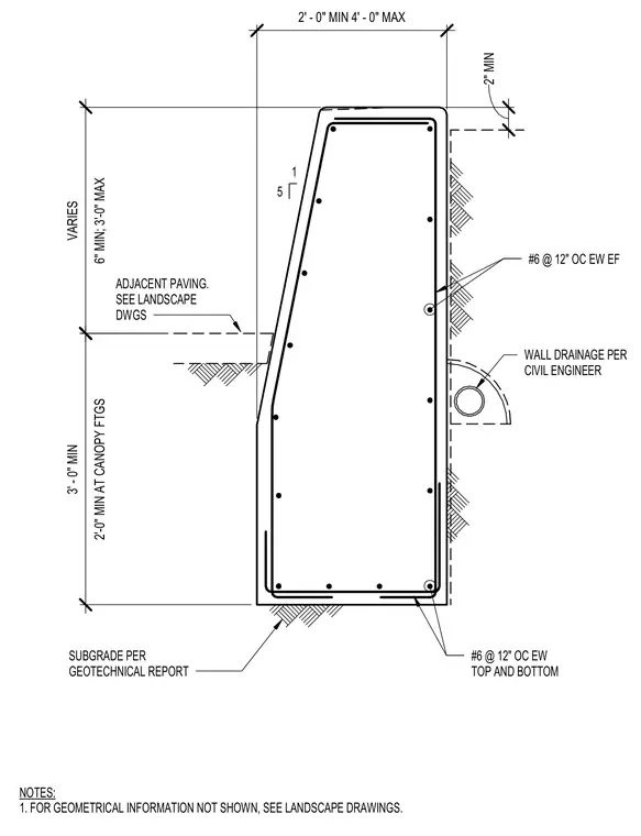
This structural section details a precast concrete battered retaining wall with reinforcing steel configured with number 6 bars at twelve inches on center each way, top and bottom, alongside number 6 bars at twelve inches on center each way. The wall rests on a subgrade prepared per geotechnical requirements and includes a wall drainage pipe specified by the civil engineer. Dimensions specify a variable height with a three foot minimum at canopy footings, a minimum two foot and maximum four foot top width, and adjacent paving levels coordinated with landscape drawings.
2' - 0" MIN 4' - 0" MAX 2" MIN 6" MIN; 3'-0" MAX VARIES 2'-0" MIN AT CANOPY FTGS 3' - 0" MIN 1 5 ADJACENT PAVING. SEE LANDSCAPE DWGS SUBGRADE PER GEOTECHNICAL REPORT WALL DRAINAGE PER CIVIL ENGINEER #6 @ 12" OC EW TOP AND BOTTOM #6 @ 12" OC EW EF NOTES: 1. FOR GEOMETRICAL INFORMATION NOT SHOWN, SEE LANDSCAPE DRAWINGS.
Members view this detail in full resolution, download the CAD files (SVG, PDF), and can adapt it in the built-in CAD editor — export DXF, DWG, or PDF.
Start membership