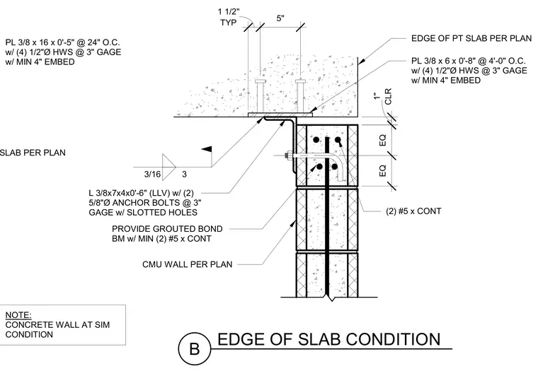
A connection exists between the top of a non-bearing concrete masonry unit wall and the edge of a post-tensioned concrete slab with a one-inch clearance gap. An embedded plate measuring 3/8 inches by 6 inches by 8 inches is anchored into the post-tensioned slab with four 1/2-inch diameter headed stud anchors spaced at a 3-inch gauge with a minimum 4-inch embedment. A structural steel angle measuring 3/8 inches by 7 inches by 4 inches by 6 inches with slotted holes connects to the masonry wall using two 5/8-inch diameter anchor bolts at a 3-inch gauge. The top of the masonry wall features a grouted bond beam reinforced with a minimum of two continuous number 5 rebars, complemented by two continuous number 5 rebars placed along the edge of the slab. A three-sixteenth-inch fillet weld secures the angle assembly, and a note indicates that a concrete wall applies at similar conditions.
TYP 1 1/2" 5" EDGE OF PT SLAB PER PLAN PL 3/8 x 6 x 0'-8" @ 4'-0" O.C. w/ (4) 1/2"Ø HWS @ 3" GAGE w/ MIN 4" EMBED (2) #5 x CONT B EDGE OF SLAB CONDITION L 3/8x7x4x0'-6" (LLV) w/ (2) 5/8"Ø ANCHOR BOLTS @ 3" GAGE w/ SLOTTED HOLES CMU WALL PER PLAN PT SLAB PER PLAN PL 3/8 x 16 x 0'-5" @ 24" O.C. w/ (4) 1/2"Ø HWS @ 3" GAGE w/ MIN 4" EMBED 3/16 3 EQ EQ CLR 1" PROVIDE GROUTED BOND BM w/ MIN (2) #5 x CONT NOTE: CONCRETE WALL AT SIM CONDITION
Members view this detail in full resolution, download the CAD files (SVG, PDF), and can adapt it in the built-in CAD editor — export DXF, DWG, or PDF.
Start membership