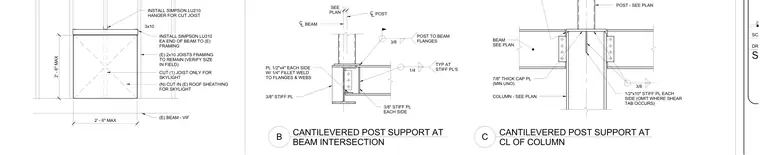
Cantilevered post supports occur at a beam intersection and column centerline. Detail B has a post supported at a beam intersection utilizing one-half-inch by four-inch plates on each side with quarter-inch fillet welds to the flanges and webs, alongside three-eighths-inch stiffener plates. Detail C has a post supported at the centerline of a column featuring a seven-eighths-inch thick cap plate, with one-half-inch by ten-inch stiffener plates on each side omitting where shear tabs occur. Additionally, framing modifications for a skylight include cutting one joist, installing Simpson LU210 hangers for cut joists, and installing Simpson LU310 hangers at each end of the beam to existing framing with existing two-by-ten joists remaining as verified in the field.
CANTILEVERED POST SUPPORT AT BEAM INTERSECTION B 3/8" STIFF PL PL 1/2"x4" EACH SIDE W/ 1/4" FILLET WELD TO FLANGES & WEBS BEAM 3/8" STIFF PL EACH SIDE POST CANTILEVERED POST SUPPORT AT CL OF COLUMN C 7/8" THICK CAP PL (MIN UNO) COLUMN - SEE PLAN BEAM SEE PLAN 1/2"x10" STIFF PL EACH SIDE (OMIT WHERE SHEAR TAB OCCURS) POST - SEE PLAN PLAN SEE 3/8 POST TO BEAM FLANGES 1/4 TYP AT STIFF PL'S 3/8 CUT (1) JOIST ONLY FOR SKYLIGHT (E) 2x10 JOISTS FRAMING TO REMAIN (VERIFY SIZE IN FIELD) (N) CUT IN (E) ROOF SHEATHING FOR SKYLIGHT 3x10 2' - 6" MAX INSTALL SIMPSON LU210 HANGER FOR CUT JOIST INSTALL SIMPSON LU310 EA END OF BEAM TO (E) FRAMING (E) BEAM - VIF 2' - 6" MAX DRAWN BY:: SCALE:: 2' SECTIONS & DETAILS
Members view this detail in full resolution, download the CAD files (SVG, PDF), and can adapt it in the built-in CAD editor — export DXF, DWG, or PDF.
Start membership