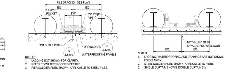
A foundation base drainage assembly is installed between steel soldier piles spaced equally per plan. A three-inch diameter perforated pipe sits within a gravel pocket atop drainboard and waterproofing panels applied to the concrete slab. A one-eighth inch thick by three-quarter inch deep sawcut filled with silicone is positioned in the slab between the pile locations. Lap splices are executed using the non-contact lap splice method with a minimum vertical spacing of eighteen inches on center. Lagging, waterproofing, and drainage are omitted in the alternate view for clarity.
EQ. EQ. NOTES: 1. LAGGING, WATERPROOFING AND DRAINAGE ARE NOT SHOWN FOR CLARITY. 2. STEEL SOLDIER PILES SHOWN, APPLICABLE TO PIERS. 3. SINGLE CURTAIN SHOWN, DOUBLE CURTAIN SIM. 1/8"THKx3/4" DEEP SAWCUT. FILL W/ SILICON PILE SPACING - SEE PLAN 2'-0" 3"Ø PERF. PIPE 3"Ø OUTLE PIPE GRAVEL POCKET WATERPROOFING PANELS DRAINBOARD EQ EQ NOTES: 1. LAGGING NOT SHOWN FOR CLARITY. 2. REFER TO WATERPROOFING DETAILS. 3. PIER SOLDIER PILES SHOWN, APPLICABLE TO STEEL PILES. 5 SS500 6 SS500 LAP SPLICES SHALL BE BY THE NON-CONTACT LAP SPLICE METHOD WITH A MIN. VERTICAL SPACING BETWEEN LAPS SHOULD OCCUR NO CLOSER THAN 18" O.C.
Members view this detail in full resolution, download the CAD files (SVG, PDF), and can adapt it in the built-in CAD editor — export DXF, DWG, or PDF.
Start membership