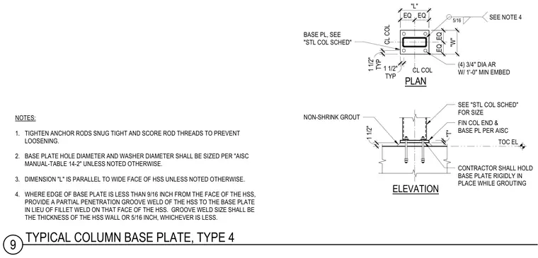
This structural detail shows a typical column base plate connection for a hollow structural section column supported on a concrete foundation. Four three-quarter-inch diameter anchor rods with one-foot minimum embedment secure the base plate, which is sized per the structural column schedule. A layer of non-shrink grout is placed beneath the base plate, and the contractor must hold the base plate rigidly in place during grouting operations. A five-sixteenth-inch fillet weld or partial penetration groove weld connects the hollow structural section to the base plate depending on the edge distance. Anchor rods are to be tightened snug tight with threaded ends scored to prevent loosening.
TOC EL (4) 3/4" DIA AR W/ 1'-0" MIN EMBED FIN COL END & BASE PL PER AISC NON-SHRINK GROUT SEE NOTE 4 5/16 NOTES: 1. TIGHTEN ANCHOR RODS SNUG TIGHT AND SCORE ROD THREADS TO PREVENT LOOSENING. 2. BASE PLATE HOLE DIAMETER AND WASHER DIAMETER SHALL BE SIZED PER "AISC MANUAL-TABLE 14-2" UNLESS NOTED OTHERWISE. 3. DIMENSION "L" IS PARALLEL TO WIDE FACE OF HSS UNLESS NOTED OTHERWISE. 4. WHERE EDGE OF BASE PLATE IS LESS THAN 9/16 INCH FROM THE FACE OF THE HSS, PROVIDE A PARTIAL PENETRATION GROOVE WELD OF THE HSS TO THE BASE PLATE IN LIEU OF FILLET WELD ON THAT FACE OF THE HSS. GROOVE WELD SIZE SHALL BE THE THICKNESS OF THE HSS WALL OR 5/16 INCH, WHICHEVER IS LESS. ELEVATION PLAN SEE "STL COL SCHED" FOR SIZE CL COL CONTRACTOR SHALL HOLD BASE PLATE RIGIDLY IN PLACE WHILE GROUTING BASE PL, SEE "STL COL SCHED" CL COL 1" 12" 10" TYP 1 1/2" EQ EQ TYP 1 1/2" EQ EQ 1 1/2" "L" "W" "T" 9 TYPICAL COLUMN BASE PLATE, TYPE 4
Members view this detail in full resolution, download the CAD files (SVG, PDF), and can adapt it in the built-in CAD editor — export DXF, DWG, or PDF.
Start membership