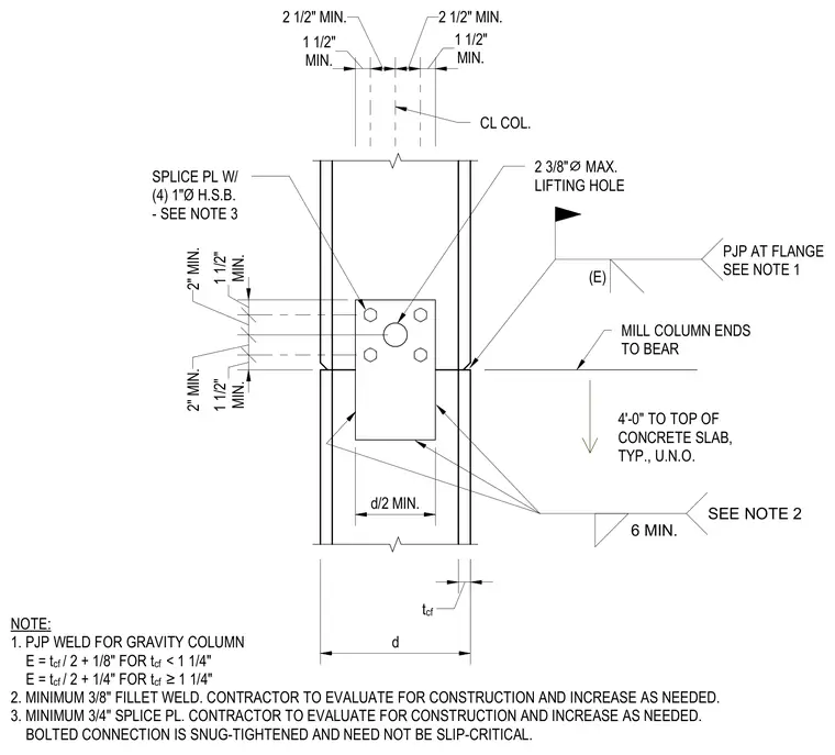
A gravity column splice connection features milled column ends designed to bear directly against one another, positioned four feet above the top of the concrete slab typically unless noted otherwise. The connection incorporates a minimum three-quarter-inch splice plate secured with four one-inch diameter high-strength bolts, specified as snug-tightened and not required to be slip-critical. The existing column flanges are joined with a partial-joint-penetration weld sized according to specific flange thickness formulas. A field weld with a minimum three-eighths-inch fillet is included, with the contractor required to evaluate and increase sizing as needed for construction loads. Additionally, a maximum two-and-three-eighths-inch diameter lifting hole is provided on the centerline of the column web.
MILL COLUMN ENDS TO BEAR 4'-0" TO TOP OF CONCRETE SLAB, TYP., U.N.O. (E) PJP AT FLANGE SEE NOTE 1 NOTE: 1. PJP WELD FOR GRAVITY COLUMN E = t cf / 2 + 1/8" FOR t cf < 1 1/4" E = t cf / 2 + 1/4" FOR t cf ≥1 1/4" 2. MINIMUM 3/8" FILLET WELD. CONTRACTOR TO EVALUATE FOR CONSTRUCTION AND INCREASE AS NEEDED. 3. MINIMUM 3/4" SPLICE PL. CONTRACTOR TO EVALUATE FOR CONSTRUCTION AND INCREASE AS NEEDED. BOLTED CONNECTION IS SNUG-TIGHTENED AND NEED NOT BE SLIP-CRITICAL. SPLICE PL W/ (4) 1"Ø H.S.B. - SEE NOTE 3 t cf MIN. 1 1/2" 2 1/2" MIN. 2 1/2" MIN. MIN. 1 1/2" d MIN. 1 1/2" 2" MIN. 2" MIN. MIN. 1 1/2" CL COL. 2 3/8" ⌀ MAX. LIFTING HOLE d/2 MIN. 6 MIN. SEE NOTE 2
Members view this detail in full resolution, download the CAD files (SVG, PDF), and can adapt it in the built-in CAD editor — export DXF, DWG, or PDF.
Start membership