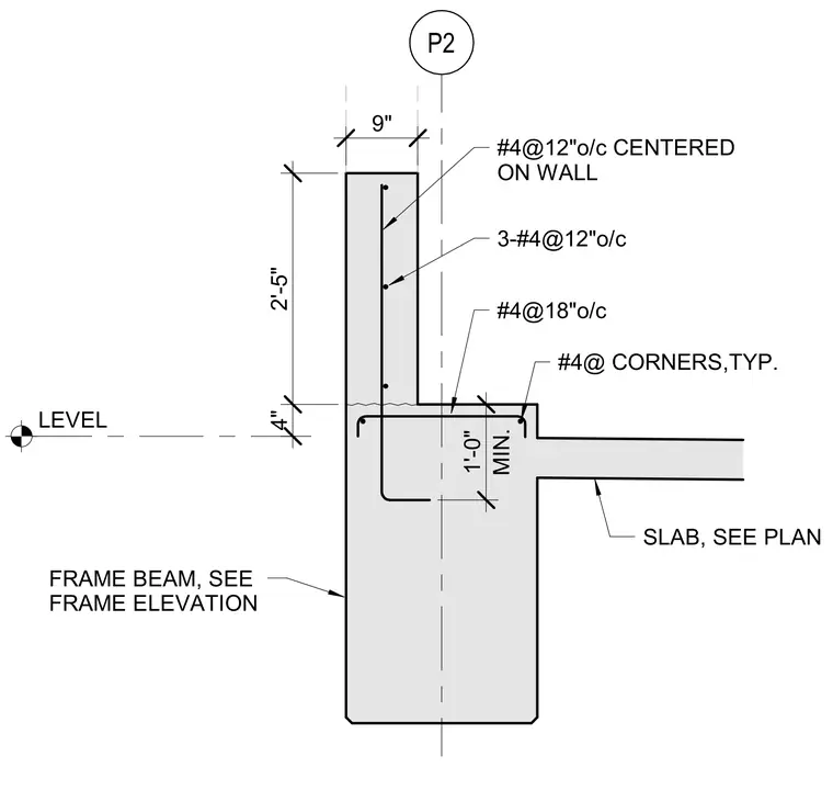
A concrete beam supports a concrete slab and a wall extension above. The wall features a nine-inch width with vertical reinforcement of number four bars at twelve inches on center centered on the wall, alongside three number four bars spaced at twelve inches on center. The horizontal slab connects to the beam with number four bars at eighteen inches on center and number four bars at corners typically, providing a minimum one-foot embedment or lap depth. The frame beam and slab layout are referenced to the respective plan and frame elevation drawings.
LEVEL 02 P2 LEVEL 2'-5" 4" 9" #4@12"o/c CENTERED ON WALL 3-#4@12"o/c MIN. 1'-0" FRAME BEAM, SEE FRAME ELEVATION #4@ CORNERS,TYP. SLAB, SEE PLAN #4@18"o/c
Members view this detail in full resolution, download the CAD files (SVG, PDF), and can adapt it in the built-in CAD editor — export DXF, DWG, or PDF.
Start membership