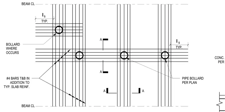
Pipe bollards are positioned per plan within a concrete slab and aligned with beam centerlines. Supplemental reinforcement consists of number 4 bars placed at the top and bottom in addition to the typical slab reinforcing. The layout indicates bollard locations occurring at designated intervals relative to structural grids.
PIPE BOLLARD PER PLAN #4 BARS T&B IN ADDITION TO TYP. SLAB REINF. BEAM CL BEAM CL A A A A BOLLARD WHERE OCCURS TYP. s l TYP. s l CONC. SLAB PER PLAN
Members view this detail in full resolution, download the CAD files (SVG, PDF), and can adapt it in the built-in CAD editor — export DXF, DWG, or PDF.
Start membership