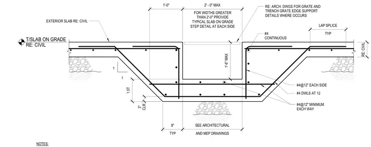
A concrete drainage trench is formed within a reinforced concrete slab on grade, featuring a depressed trench profile with a maximum one foot six inch depth and a maximum two foot width. Continuous number four reinforcing bars run horizontally along the trench profile, supplemented by number four dowels spaced at twelve inches on center. The trench perimeter includes number four reinforcing bars spaced at twelve inches each way within the exterior slab and side slopes. Lap splices are detailed typical throughout the slab reinforcement. For trench widths greater than two feet, a typical slab on grade step detail is provided at each side per civil drawings.
1 1 #4 CONTINUOUS NOTES: #4@12" MINIMUM EACH WAY #4@12" EACH SIDE EXTERIOR SLAB RE: CIVIL T/SLAB ON GRADE RE: CIVIL TYP 8" AND MEP DRAWINGS SEE ARCHITECTURAL 1.5T 1'-0" 2' - 0" MAX FOR WIDTHS GREATER THAN 2'-0" PROVIDE TYPICAL SLAB ON GRADE STEP DETAIL AT EACH SIDE RE: CIVIL 1'-6" MAX CLR 3" #4 DWLS AT 12 RE: ARCH. DWGS FOR GRATE AND TRENCH GRATE EDGE SUPPORT DETAILS WHERE OCCURS TYP LAP SPLICE
Members view this detail in full resolution, download the CAD files (SVG, PDF), and can adapt it in the built-in CAD editor — export DXF, DWG, or PDF.
Start membership