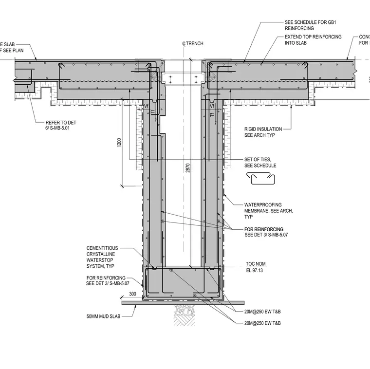
This structural section details a cast-in-place concrete trench intersecting with concrete floor slabs on either side. The trench walls are reinforced vertically and horizontally with 20M reinforcing bars at 250 millimeters spacing each way top and bottom, complemented by a set of ties sized per the structural schedule. A cementitious crystalline waterstop system is specified at the base joint, combined with an exterior waterproofing membrane and rigid insulation applied to the wall exterior. The assembly rests on a 50 millimeter mud slab over a compacted subbase, with top reinforcing extending continuously into the adjacent floor slabs.
Tf Vf Tf Vf CLTRENCH RIGID INSULATION SEE ARCH TYP SEE SCHEDULE FOR GB1 REINFORCING EXTEND TOP REINFORCING INTO SLAB SET OF TIES, SEE SCHEDULE FOR REINFORCING 20M@250 EW T&B CEMENTITIOUS CRYSTALLINE WATERSTOP SYSTEM, TYP CONCRETE SLAB FOR REINF SEE PLAN TOC NOM CONCRETE SLAB FOR REINF SEE PLAN EL 97.13 FOR REINFORCING REFER TO DET 6/ S-MB-5.01 550 2870 SEE DET 3/ S-MB-5.07 FOR REINFORCING SEE DET 3/ S-MB-5.07 20M@250 EW T&B 50MM MUD SLAB WATERPROOFING MEMBRANE, SEE ARCH, TYP 1200 300
Members view this detail in full resolution, download the CAD files (SVG, PDF), and can adapt it in the built-in CAD editor — export DXF, DWG, or PDF.
Start membership