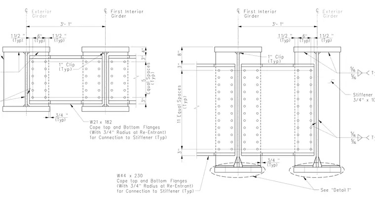
An end diaphragm connection occurs between exterior and first interior steel girders spaced three feet one inch apart. The framing members utilize W21x182 and W44x230 wide flange steel shapes with top and bottom flanges coped to accommodate connection to stiffener plates, incorporating a three-quarters inch radius at re-entrant cuts. Three-quarters inch by ten-inch stiffener plates are welded to the girder webs with five-sixteenths inch fillet welds. One-inch typical clips facilitate the structural connection between the diaphragm beams and the girder stiffeners.
C C 3’- 1" (Typ) 1 1/2 " (Typ) 6" (Typ) 1 1/2 " 3 " 4 " 3 " ( T yp ) E qu a l S p ace s 5 (Typ) 3/4 " C C 3’- 1" Girder L First Interior Girder L First Interior ( T yp ) 11 E qu a l S p ace s 8 " 3 " 3 " (Typ) 1 1/2 " (Typ) 6" (Typ) 1 1/2 " Typ Typ (Typ) 3/4 " 3/4" x 10"(Typ) Stiffener Plate See "Detail 1" L Exterior Girder L Exterior Girder (Typ) 1" Clip (Typ) 1" Clip for Connection to Stiffener (Typ) (With 3/4" Radius at Re-Entrant) Cope top and Bottom Flanges W21 x 182 for Connection to Stiffener (Typ) (With 3/4" Radius at Re-Entrant) Cope top and Bottom Flanges W44 x 230
Members view this detail in full resolution, download the CAD files (SVG, PDF), and can adapt it in the built-in CAD editor — export DXF, DWG, or PDF.
Start membership