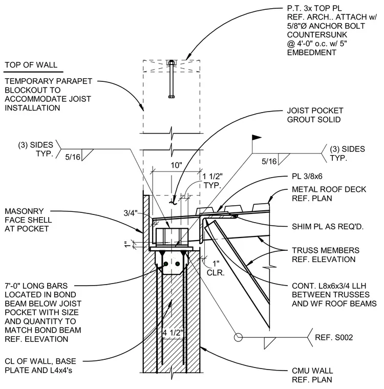
A continuous angle L8x6x3/4 spans between the roof trusses and wide-flange roof beams, bearing on a 3/8-inch by 6-inch plate over a solid grouted masonry bond beam. The masonry wall includes 7-foot long reinforcing bars located in the bond beam directly below the joist pocket. Truss members frame into the assembly, with a 5/16-inch fillet weld applied to three sides typically. A pressure-treated 3x top plate is anchored to the top of the wall with 5/8-inch diameter countersunk anchor bolts at 4 feet on center with a 5-inch embedment, accommodating a temporary parapet blockout for joist installation.
7'-0" LONG BARS LOCATED IN BOND BEAM BELOW JOIST POCKET WITH SIZE AND QUANTITY TO MATCH BOND BEAM REF. ELEVATION CMU WALL REF. PLAN METAL ROOF DECK REF. PLAN 5/16 (3) SIDES TYP. 4 1/2" TRUSS MEMBERS REF. ELEVATION MASONRY FACE SHELL AT POCKET JOIST POCKET GROUT SOLID REF. S002 TEMPORARY PARAPET BLOCKOUT TO ACCOMMODATE JOIST INSTALLATION P.T. 3x TOP PL REF. ARCH.. ATTACH w/ 5/8"Ø ANCHOR BOLT COUNTERSUNK @ 4'-0" o.c. w/ 5" EMBEDMENT TOP OF WALL 5/16 (3) SIDES TYP. CLR. 1" 1" CL OF WALL, BASE PLATE AND L4x4's 10" 3/4" TYP. 1 1/2" PL 3/8x6 SHIM PL AS REQ'D. CONT. L8x6x3/4 LLH BETWEEN TRUSSES AND WF ROOF BEAMS
Members view this detail in full resolution, download the CAD files (SVG, PDF), and can adapt it in the built-in CAD editor — export DXF, DWG, or PDF.
Start membership