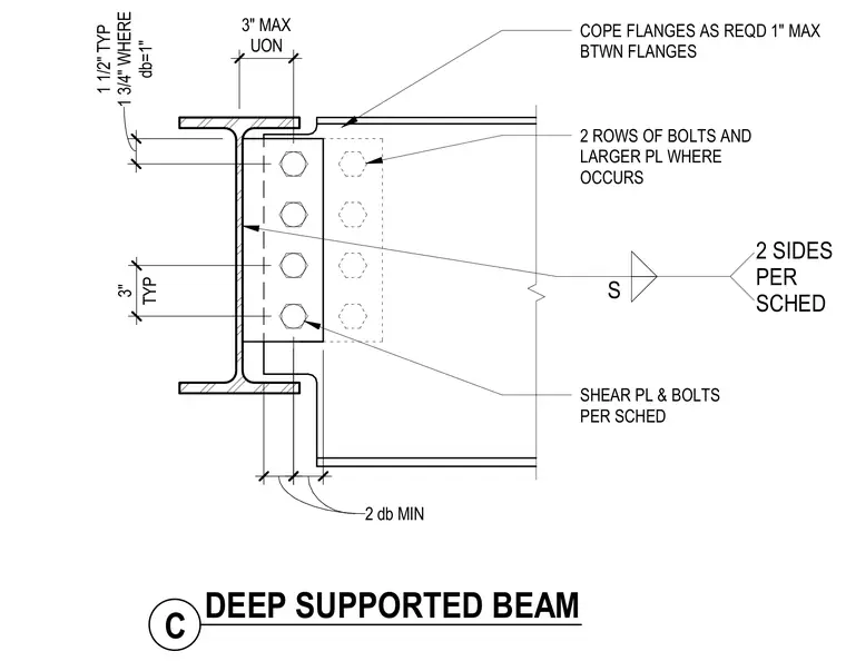
A supported steel beam frames into a supporting member using a shear plate welded on two sides per schedule and bolted with two rows of bolts. The supported beam features coped flanges to clear the support with a one-inch maximum clearance between the flanges. Bolt spacing includes a one-and-one-half-inch typical edge distance, one-and-three-quarter-inch distance where bolt diameter equals one inch, and a three-inch typical vertical spacing with a two-bolt-diameter minimum. A three-inch maximum dimension applies unless otherwise noted, and larger plates are used where required.
2 ROWS OF BOLTS AND LARGER PL WHERE OCCURS SHEAR PL & BOLTS PER SCHED db=1" 1 1/2" TYP 1 3/4" WHERE 2 db MIN 3" MAX UON TYP 3" C DEEP SUPPORTED BEAM COPE FLANGES AS REQD 1" MAX BTWN FLANGES S 2 SIDES PER SCHED
Members view this detail in full resolution, download the CAD files (SVG, PDF), and can adapt it in the built-in CAD editor — export DXF, DWG, or PDF.
Start membership