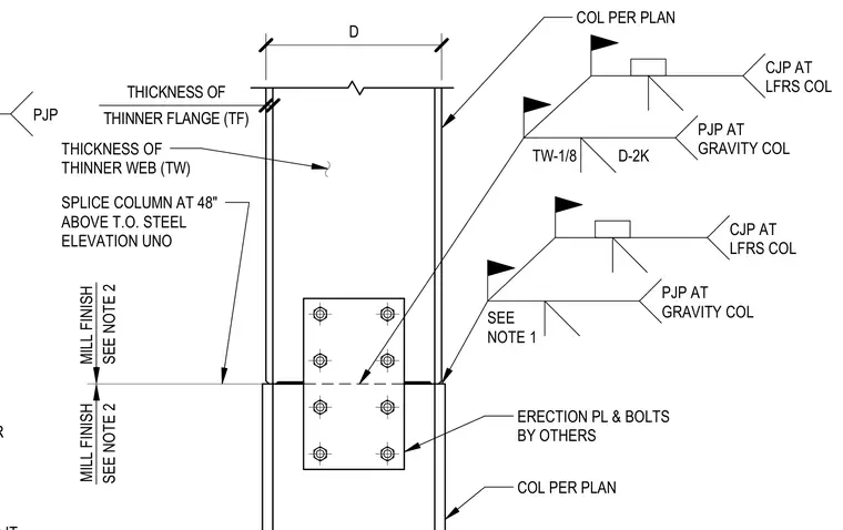
A steel column splice connection is positioned forty-eight inches above the top of steel elevation unless noted otherwise. The lower and upper columns align per plan with mill finish requirements specified by notes. An erection plate and bolts furnished by others secure the joint temporarily during alignment. The connection utilizes either complete joint penetration welds at lateral force-resisting system columns or partial joint penetration welds at gravity columns, with backing bars applied as required based on the thickness of the thinner flange and web.
BACKING BAR PJP THICKNESS OF THINNER WEB (TW) THINNER FLANGE (TF) THICKNESS OF SPLICE COLUMN AT 48" ABOVE T.O. STEEL ELEVATION UNO MILL FINISH SEE NOTE 2 MILL FINISH SEE NOTE 2 ERECTION PL & BOLTS BY OTHERS D TW-1/8 D-2K PJP AT GRAVITY COL CJP AT LFRS COL PJP AT GRAVITY COL SEE NOTE 1 CJP AT LFRS COL COL PER PLAN COL PER PLAN
Members view this detail in full resolution, download the CAD files (SVG, PDF), and can adapt it in the built-in CAD editor — export DXF, DWG, or PDF.
Start membership