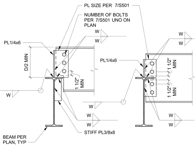
These connections utilize a one-quarter inch by six inch plate welded to the supporting beam web to receive the supported beam. The supported beam is bolted to this plate with the number of bolts and plate size determined by reference to sheet 7/S501 unless noted otherwise on the plan. A three-eighths inch by eight inch stiffener plate is welded to the supporting beam web directly beneath the connection to provide additional bearing support. The connection requires a minimum one and one-half inch clearance between the supported beam flange and the supporting beam flange. All welds are specified as fillet welds, with the size indicated by the weld symbol.
Members view this detail in full resolution, download the CAD files (SVG, PDF), and can adapt it in the built-in CAD editor — export DXF, DWG, or PDF.
Start membership