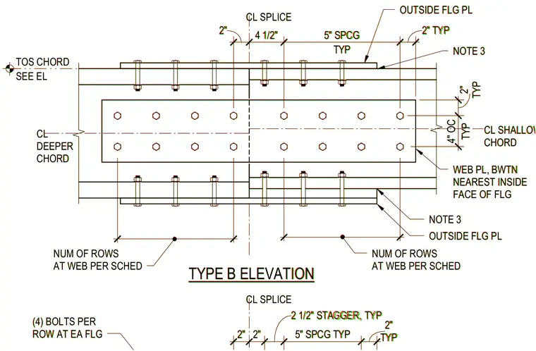
A bolted chord splice connection joins a deeper chord to a shallower chord member. The assembly features outside flange plates positioned between the nearest inside face of the flange, alongside web plates with the number of rows determined per schedule. Fastener layout includes four bolts per row at each flange with a two-inch and two-and-a-half-inch typical stagger and five-inch typical spacing. Additional dimensions include a four-inch on-center typical spacing at the web plate and two-inch edge distances. The connection aligns the centerline of the splice with reference to top of steel elevations.
TYPE B ELEVATION CL SPLICE CL SHALLOWER CHORD OUTSIDE FLG PL WEB PL, BWTN NEAREST INSIDE FACE OF FLG NOTE 3 OUTSIDE FLG PL NUM OF ROWS AT WEB PER SCHED NUM OF ROWS AT WEB PER SCHED 2" 4 1/2" TYP 5" SPCG 2" TYP 15" 15" (4) BOLTS PER ROW AT EA FLG CL SPLICE 2" 2" 2 1/2" STAGGER, TYP 5" SPCG TYP TYP 2" TYP 4" OC TYP 2" CL DEEPER CHORD SEE EL TOS CHORD NOTE 3 TYPE B ELEVATION CL SPLICE CL SHALLOWER CHORD OUTSIDE FLG PL WEB PL, BWTN NEAREST INSIDE FACE OF FLG NOTE 3 OUTSIDE FLG PL NUM OF ROWS AT WEB PER SCHED NUM OF ROWS AT WEB PER SCHED 2" 4 1/2" TYP 5" SPCG 2" TYP 15" 15" (4) BOLTS PER ROW AT EA FLG CL SPLICE 2" 2" 2 1/2" STAGGER, TYP 5" SPCG TYP TYP 2" TYP 4" OC TYP 2" CL DEEPER CHORD SEE EL TOS CHORD NOTE 3
Members view this detail in full resolution, download the CAD files (SVG, PDF), and can adapt it in the built-in CAD editor — export DXF, DWG, or PDF.
Start membership