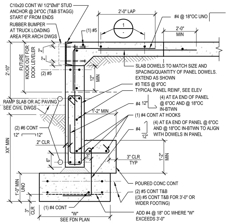
A reinforced concrete footing and foundation wall supports a slab or ramp with a truck loading dock detail. The continuous concrete footing includes bottom and top reinforcing bars with a three-inch minimum clear cover and optional widening reinforcement based on dimension W. The foundation wall extends upward with vertical and horizontal reinforcing bars, number three ties at nine inches on center, and slab dowels matching the panel reinforcement size and spacing with a two-foot lap. A continuous C10x20 channel with half-inch diameter by eight-inch stud anchors at twenty-four inches on center staggered is embedded at the top edge, positioned to accommodate a rubber bumper at the truck loading area per architectural drawings. A designated two-foot ten-inch vertical space provides a future knockout for a dock leveler, framed by continuous reinforcing bars.
RAMP SLAB OR AC PAVING SEE CIVIL DWGS 3" CLR TYP (1) #4 CONT AT HOOKS POURED CONC CONT 1'-2" MIN 12" #4 12" 1'-2" MIN 1'-0" MIN UNO 3" CLR 2" CLR 6" 3" (4) AT EA END OF PANEL @ 6"OC AND @ 18"OC IN-BTWN TO ALIGN WITH DOWELS IN PANEL #4 (4) AT EA END OF PANEL @ 6"OC AND @ 18"OC IN-BTWN 1 - 2'-0" LAP 2'-0" MIN SLAB DOWELS TO MATCH SIZE AND SPACING/QUANTITY OF PANEL DOWELS. EXTEND AS SHOWN #4 @ 18"OC UNO 12" MIN ADD #4 @ 18" OC WHERE "W" EXCEEDS 3'-0" (2) #5 CONT T&B ((3) #5 CONT T&B FOR 3'-0" OR WIDER FOOTING) XX" MIN 2'-10" FUTURE KNOCK OUT FOR DOCK LEVELER (2) #5 2" 2" C10x20 CONT W/ 1/2 "Øx8" STUD ANCHOR @ 24"OC (T&B STAGG) START 6" FROM ENDS RUBBER BUMPER AT TRUCK LOADING AREA PER ARCH DWGS (1) #5 (2) #6 CONT 12" 12" #3 TIES @ 9"OC TYPICAL PANEL REINF, SEE ELEV "W" SEE FDN PLAN (1) #4 CONT
Members view this detail in full resolution, download the CAD files (SVG, PDF), and can adapt it in the built-in CAD editor — export DXF, DWG, or PDF.
Start membership