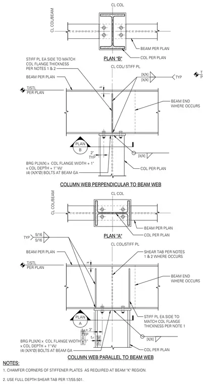
Steel beam to column connections feature the column web oriented both perpendicular and parallel to the beam web. The assembly incorporates stiffener plates on each side matching the column flange thickness, with corners chamfered as required at the beam k-region. A bearing plate sized to the column flange width plus one inch and column depth plus one inch is secured with four bolts at the beam gauge. Shear tabs and fillet welds are provided per structural notes and plans.
PLAN A PLAN B STIFF PL EA SIDE TO MATCH COL FLANGE THICKNESS PER NOTES 1 & 2 TYP 2" BEAM PER PLAN [X/X] [X/X] TYP BEAM PER PLAN 5/16 5/16 TYP k k BRG PL[X/X] x COL FLANGE WIDTH + 1" x COL DEPTH + 1" W/ (4) [X/X"Ø] BOLTS AT BEAM GA COL PER PLAN [X/X] SHEAR TAB PER NOTES 1 & 2 WHERE OCCURS T/STL PER PLAN CL COL/ STIFF PL COLUMN WEB PERPENDICULAR TO BEAM WEB T/STL PER PLAN COLUMN WEB PARALLEL TO BEAM WEB CL COL/STIFF PL BEAM END WHERE OCCURS BEAM END WHERE OCCURS STIFF PL EA SIDE TO MATCH COL FLANGE THICKNESS PER NOTE 1 [X/X] BRG PL[X/X] x COL FLANGE WIDTH + 1" x COL DEPTH + 1" W/ (4) [X/X"Ø] BOLTS AT BEAM GA COL PER PLAN NOTES: 1. CHAMFER CORNERS OF STIFFENER PLATES AS REQUIRED AT BEAM "K" REGION. 2. USE FULL DEPTH SHEAR TAB PER 17/S5.501. PLAN "A" BEAM PER PLAN COL PER PLAN CL COL CL COL/BEAM CL COL/BEAM PLAN "B" CL COL BEAM PER PLAN COL PER PLAN t cf t cf + 3" TYP T/STL PER PLAN
Members view this detail in full resolution, download the CAD files (SVG, PDF), and can adapt it in the built-in CAD editor — export DXF, DWG, or PDF.
Start membership