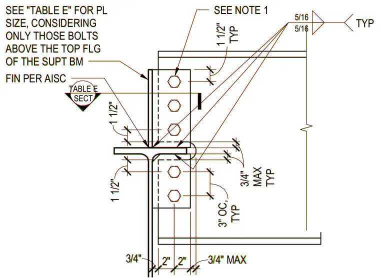
A supported steel beam frames into a supporting steel beam via a connection plate sized per Table E. The shear plate is welded to the supporting beam with typical five-sixteenths inch fillet welds and secured to the supported beam web with bolts spaced at three inches on center typically. Edge distances and maximum clearances are dimensioned relative to the top flange of the supporting beam. Only bolts positioned above the top flange of the supporting beam are considered for plate sizing requirements.
SECT TABLE E 3 /4" 3 /4" 3/4" MAX TYP 3/4" MAX FIN PER AISC 1 1/2" 2" 2" 3/4" TYP 5/16 5/16 1 1/2" 3 " T YP TYP 1 1/2" SEE NOTE 1 SEE "TABLE E" FOR PL SIZE, CONSIDERING ONLY THOSE BOLTS ABOVE THE TOP FLG OF THE SUPT BM 3" OC, TYP SECT TABLE E 3/4" 3/4" 3/4" MAX TYP 3/4" MAX FIN PER AISC 1 1/2" 2" 2" 3/4" TYP 5/16 5/16 1 1/2" 3" TYP TYP 1 1/2" SEE NOTE 1 SEE "TABLE E" FOR PL SIZE, CONSIDERING ONLY THOSE BOLTS ABOVE THE TOP FLG OF THE SUPT BM 3" OC, TYP
Members view this detail in full resolution, download the CAD files (SVG, PDF), and can adapt it in the built-in CAD editor — export DXF, DWG, or PDF.
Start membership