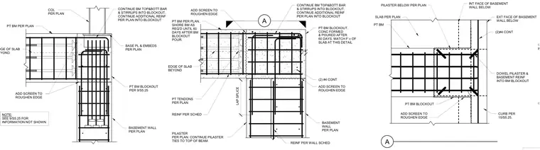
A post-tensioned beam connection occurs at a basement wall and column with a post-tensioned beam blockout. The assembly features continuous top and bottom beam bars and stirrups extending into the blockout, along with two continuous number four reinforcing bars. The concrete for the blockout is formed and poured sixty days after the initial beam blockout pour, matching the compressive strength of the slab. The beam requires shoring until sixty days after the blockout pour, with post-tendons and reinforcement sized per plan. The interface includes roughened edges created by adding a screen, lap splices, and dowels tying the pilaster and basement reinforcement into the beam blockout.
PT BM PER PLAN. SHORE BM AS REQ'D UNTIL 60 DAYS AFTER BM BLOCKOUT POUR. BASEMENT WALL PER PLAN PT BM BLOCKOUT. CONC FORMED & POURED AFTER 60 DAYS. MATCH F`c OF SLAB AT THIS DETAIL ADD SCREEN TO ROUGHEN EDGE PT TENDONS PER PLAN A PILASTER PER PLAN. CONTINUE PILASTER TIES TO TOP OF BEAM ADD SCREEN TO ROUGHEN EDGE REINF PER WALL SCHED SLAB PER PLAN PT BM PILASTER BELOW PER PLAN REINF PER SCHED A (2) #4 CONT (2)#4 CONT CURB PER 15/S5.25. ADD SCREEN TO ROUGHEN EDGE CONTINUE BM TOP&BOTT BAR & STIRRUPS INTO BLOCKOUT. CONTINUE ADDITIONAL REINF PER PLAN INTO BLOCKOUT DOWEL PILASTER & BASEMENT REINF INTO BM BLOCKOUT EXT FACE OF BASEMENT WALL BELOW INT FACE OF BASEMENT WALL BELOW PT BM BLOCKOUT EDGE OF SLAB BEYOND LAP SPLICE 2 1/8" NOTE: SEE 9/S5.25 FOR INFORMATION NOT SHOWN COL PER PLAN PT BM PER PLAN BASEMENT WALL PER PLAN BASE PL & EMBEDS PER PLAN PT BM BLOCKOUT PER 9/S5.25 ADD SCREEN TO ROUGHEN EDGE CONTINUE BM TOP&BOTT BAR & STIRRUPS INTO BLOCKOUT. CONTINUE ADDITIONAL REINF PER PLAN INTO BLOCKOUT EDGE OF SLAB BEYOND Project
Members view this detail in full resolution, download the CAD files (SVG, PDF), and can adapt it in the built-in CAD editor — export DXF, DWG, or PDF.
Start membership