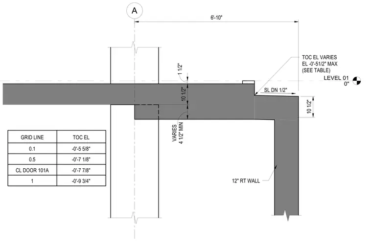
A concrete slab features a 1/2-inch downward step and a varying top of concrete elevation with a maximum of -0'-5 1/2 inches as specified in the included grid line table. The slab is supported by a twelve-inch reinforced concrete wall at grid line A, maintaining a minimum four and one-half inch bearing overlap. Vertical dimensions indicate a ten and one-half inch slab thickness with a one and one-half inch upper recess.
LEVEL 01 0" A 1 1/2" 10 1/2" 4 1/2" MIN VARIES 6'-10" TOC EL VARIES EL -0'-51/2" MAX (SEE TABLE) SL DN 1/2" 10 1/2" 12" RT WALL GRID LINE TOC EL 0.1 0.5 CL DOOR 101A 1 -0'-5 5/8" -0'-7 1/8" -0'-7 7/8" -0'-9 3/4"
Members view this detail in full resolution, download the CAD files (SVG, PDF), and can adapt it in the built-in CAD editor — export DXF, DWG, or PDF.
Start membership