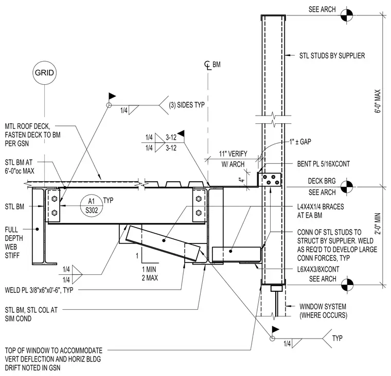
A typical exterior roof parapet assembly features a steel beam framing system supporting a metal roof deck. A structural steel beam spaced at a maximum of six feet on center is connected with full-depth web stiffeners and a three-eighths by six by six-inch weld plate. The parapet wall consists of continuous steel studs supported by continuous bent plates and continuous angle connections designed to accommodate vertical deflection and horizontal building drift. Bracing angles measuring four by four by one-quarter inches are provided at each steel beam, accompanied by a continuous angle connection for the window system where applicable. Fillet welds of one-quarter inch are specified for connections on three sides as indicated.
4" S302 A1 BM GRID W/ ARCH 11" VERIFY 1" ± GAP SEE ARCH SEE ARCH DECK BRG SEE ARCH 2'-0" MIN 6'-0" MAX STL BM AT 6'-0"oc MAX FULL DEPTH WEB STIFF WELD PL 3/8"x6"x0'-6", TYP TOP OF WINDOW TO ACCOMMODATE VERT DEFLECTION AND HORIZ BLDG DRIFT NOTED IN GSN MTL ROOF DECK, FASTEN DECK TO BM PER GSN L4X4X1/4 BRACES AT EA BM WINDOW SYSTEM (WHERE OCCURS) L6X4X3/8XCONT CONN OF STL STUDS TO STRUCT BY SUPPLIER. WELD AS REQ'D TO DEVELOP LARGE CONN FORCES, TYP BENT PL 5/16XCONT STL STUDS BY SUPPLIER 1/4 1/4 3-12 3-12 TYP 1/4 TYP (3) SIDES TYP 1/4 STL BM, STL COL AT SIM COND STL BM 1 1 MIN 2 MAX 1/4 1/4
Members view this detail in full resolution, download the CAD files (SVG, PDF), and can adapt it in the built-in CAD editor — export DXF, DWG, or PDF.
Start membership