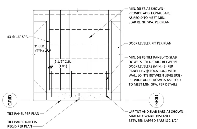
A concrete slab reinforced with number three bars spaced at sixteen inches on center, with a three-inch typical clearance. A minimum of six number three bars are provided as shown, with additional bars added as required to meet minimum slab reinforcement spacing per plan. At the interface with the tilt-up panel, a minimum of four number five dowels are installed between dock levelers, with a minimum of two dowels per panel leg at locations featuring wall joints. These dowels are lapped with the slab reinforcement, maintaining a maximum allowable distance of two and one-half inches between lapped bars. All tilt-up panel joints are required per plan.
GRID MIN. (6) #3 AS SHOWN - PROVIDE ADDITIONAL BARS AS REQ'D TO MEET MIN. SLAB REINF. SPA. PER PLAN DOCK LEVELER PIT PER PLAN MIN. (4) #5 TILT PANEL-TO-SLAB DOWELS PER DETAILS BETWEEN DOCK LEVELERS (MIN. (2) PER PANEL LEG @ LOCATIONS WITH WALL JOINTS BETWEEN LEVELERS) - PROVIDE ADD'L DOWELS AS REQ'D TO MEET MIN. SPA. PER DETAILS LAP TILT AND SLAB BARS AS SHOWN - MAX ALLOWABLE DISTANCE (TYP.) 2 1/2" CLR.
Members view this detail in full resolution, download the CAD files (SVG, PDF), and can adapt it in the built-in CAD editor — export DXF, DWG, or PDF.
Start membership