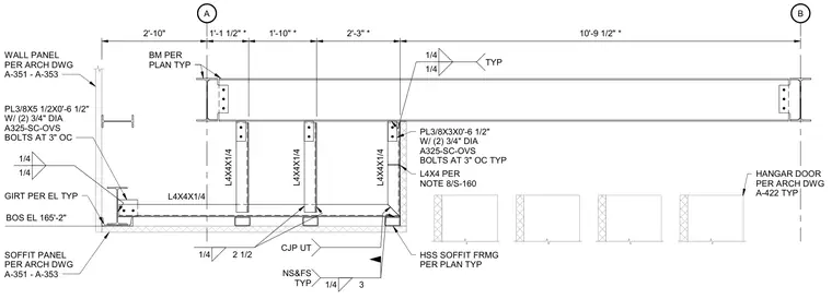
Hollow structural section soffit framing spans between grid lines A and B, featuring intermediate L4x4x1/4 angle hangers and supports. Connection plates include 3/8-inch by 3-inch by 6-1/2-inch plates secured with two 3/4-inch diameter A325 slip-critical oversized bolts at 3 inches on center. Additional support uses L4x4 angles per structural note 8/S-160 and girts located at bottom of steel elevation 165'-2". Welds include 1/4-inch fillet welds, typical near side and far side, along with complete joint penetration welds with ultrasonic testing where indicated. Wall panels, soffit panels, and hangar doors interface with the assembly per architectural drawings.
A B 2'-10" 1'-1 1/2" * 1'-10" * 2'-3" * 10'-9 1/2" * GIRT PER EL TYP BOS EL 165'-2" PL3/8X3X0'-6 1/2" W/ (2) 3/4" DIA A325-SC-OVS BOLTS AT 3" OC TYP L4X4 PER NOTE 8/S-160 S-160 1/4 1/4 TYP 1/4 3 NS&FS TYP CJP UT HSS SOFFIT FRMG PER PLAN TYP 1/4 2 1/2 L4X4X1/4 L4X4X1/4 L4X4X1/4 1/4 1/4 PL3/8X5 1/2X0'-6 1/2" W/ (2) 3/4" DIA A325-SC-OVS BOLTS AT 3" OC WALL PANEL PER ARCH DWG A-351 - A-353 HANGAR DOOR PER ARCH DWG A-422 TYP SOFFIT PANEL PER ARCH DWG A-351 - A-353 L4X4X1/4 BM PER PLAN TYP
Members view this detail in full resolution, download the CAD files (SVG, PDF), and can adapt it in the built-in CAD editor — export DXF, DWG, or PDF.
Start membership