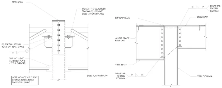
A steel channel drag connection at a frame line features a steel beam framing into a steel column with a one-half-inch by six-inch by eleven-inch steel girder seat outfitted with two one-half-inch by six-inch by eight-inch steel stiffener plates. Two three-quarter-inch diameter A325-N bolts fasten the assembly on the beam gauge, while a three-quarter-inch by six-inch by zero-foot-six-inch stabilizer plate is provided typically at girders. A one-quarter-inch cap plate tops the column, and shear tabs connect the steel beams to the steel column. Bottom chords are left unwelded to the stabilizer plate typically unless noted otherwise, and angle braces are installed per plan.
STEEL JOIST PER PLAN STEEL COLUMN STEEL BEAM STEEL BEAM 1/4" CAP PLATE ANGLE BRACE PER PLAN SHEAR TAB TO STEEL COLUMN SHEAR TAB TO STEEL COLUMN NOTE: DO NOT WELD BOT CHORDS TO STABILIZER PLATE - TYP. (U.N.O.) STEEL BEAM 3/4" x 6" x 0'-6" STABILIZER PLATE - TYP @ GIRDERS (2) 3/4" DIA. A325-N BOLTS ON BEAM GAGE 1/2"x6"x11" STEEL GIRDER SEAT W/ (2) 1/2"x6"x8" STEEL STIFFENER PLATES
Members view this detail in full resolution, download the CAD files (SVG, PDF), and can adapt it in the built-in CAD editor — export DXF, DWG, or PDF.
Start membership