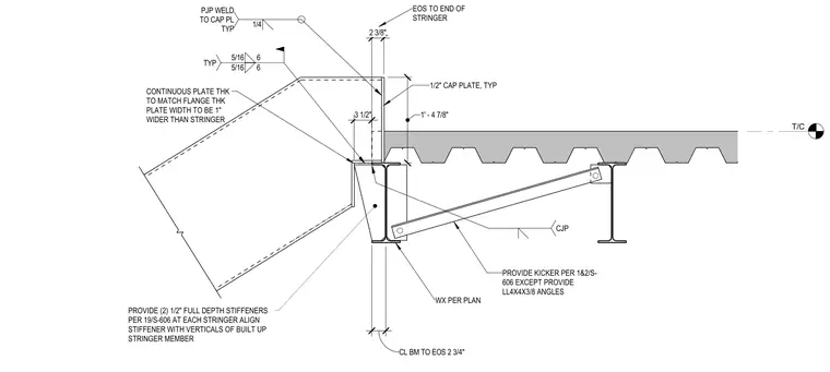
The stair stringer frames into a supporting steel beam with a one-half inch cap plate and a continuous plate whose thickness matches the flange thickness and whose width extends one inch wider than the stringer. Two one-half inch full depth stiffeners align with the verticals of the built-up stringer member. A kicker angle composed of LL4x4x3/8 angles ties the assembly back to the adjacent beam, secured with complete joint penetration welds. Additional five-sixteenths fillet welds tie the connection together, with a one-quarter inch partial joint penetration weld securing the cap plate. Dimensions locate the centerline of the beam two and three-quarters inches from the end of the stringer, with a one foot four and seven-eighths inch dimension referencing the kicker positioning.
T/C CONTINUOUS PLATE THK TO MATCH FLANGE THK PLATE WIDTH TO BE 1" WIDER THAN STRINGER PROVIDE (2) 1/2" FULL DEPTH STIFFENERS PER 19/S-606 AT EACH STRINGER ALIGN STIFFENER WITH VERTICALS OF BUILT UP STRINGER MEMBER EOS TO END OF STRINGER 1/2" CAP PLATE, TYP 3 1/2" CL BM TO EOS 2 3/4" WX PER PLAN 5/16 6 5/16 6 TYP CJP 1/4 PJP WELD TO CAP PL TYP PROVIDE KICKER PER 1&2/S- 606 EXCEPT PROVIDE LL4X4X3/8 ANGLES 1' - 4 7/8" 2 3/8"
Members view this detail in full resolution, download the CAD files (SVG, PDF), and can adapt it in the built-in CAD editor — export DXF, DWG, or PDF.
Start membership