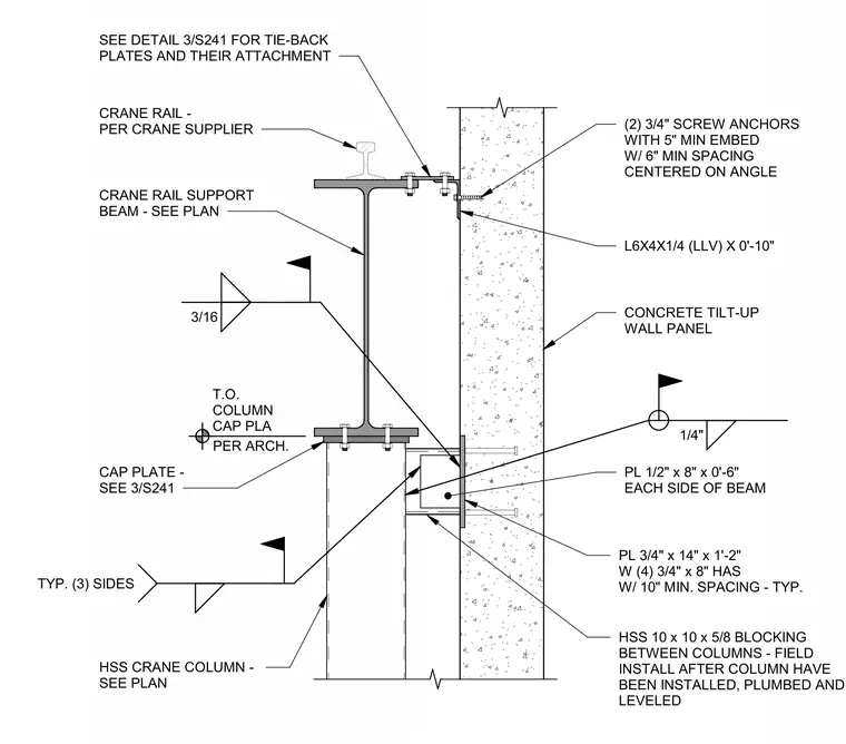
The assembly features a hollow structural section crane column supported by a three-quarter-inch by fourteen-inch by one-foot-two-inch plate anchored to the concrete tilt-up wall panel with four three-quarter-inch headed anchor studs at ten-inch minimum spacing. A ten-by-ten-by-five-eighths-inch hollow structural section blocking is installed between columns after the columns are plumbed and leveled. The crane rail support beam is connected to the column via a cap plate and to the wall panel using an L6x4x1/4 angle, which is secured with two three-quarter-inch screw anchors at five-inch minimum embedment and six-inch minimum spacing. Half-inch by eight-inch by six-inch plates are welded to each side of the beam with a quarter-inch fillet weld. The crane rail itself is installed per the crane supplier's specifications, with tie-back plates attached as indicated in detail 3/S241.
Members view this detail in full resolution, download the CAD files (SVG, PDF), and can adapt it in the built-in CAD editor — export DXF, DWG, or PDF.
Start membership