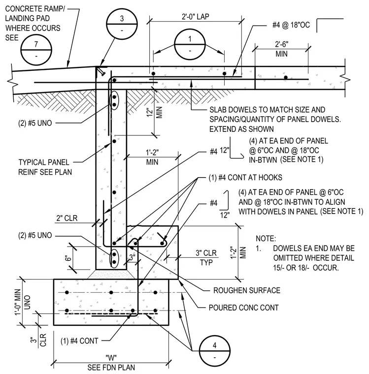
A cast-in-place concrete footing and stem wall support a concrete slab and ramp assembly with specific reinforcing dowels. The footing features a width "W" sized per foundation plan with a one-inch minimum clearance and two number-four continuous bars. The stem wall ties into the footing with slab dowels sized to match panel dowels, extending into the slab with a two-foot-zero-inch lap and a two-foot-six-inch minimum extension. Number-five bars run horizontally as indicated, with a three-inch clearance typical and two-inch clearance at specified locations. A concrete ramp or landing pad occurs where noted, tied with number-four bars at eighteen inches on center and twelve-inch minimum development. Dowels at each end may be omitted where specific details occur, and cold joint surfaces are roughened for bond.
3" CLR TYP (1) #4 CONT AT HOOKS 1'-2" MIN 12" #4 12" 1'-2" MIN 1'-0" MIN UNO 3" CLR (2) #5 UNO 2" CLR 6" 3" (4) AT EA END OF PANEL @ 6"OC AND @ 18"OC IN-BTWN TO ALIGN WITH DOWELS IN PANEL #4 (4) AT EA END OF PANEL @ 6"OC AND @ 18"OC IN-BTWN 4 - 1 - 2'-0" LAP 2'-6" MIN SLAB DOWELS TO MATCH SIZE AND SPACING/QUANTITY OF PANEL DOWELS. EXTEND AS SHOWN (2) #5 UNO TYPICAL PANEL REINF SEE PLAN CONCRETE RAMP/ LANDING PAD WHERE OCCURS SEE 7 - #4 @ 18"OC 12" MIN 3 - "W" SEE FDN PLAN (1) #4 CONT (SEE NOTE 1) (SEE NOTE 1) NOTE: 1. DOWELS EA END MAY BE OMITTED WHERE DETAIL 15/- OR 18/- OCCUR. POURED CONC CONT ROUGHEN SURFACE
Members view this detail in full resolution, download the CAD files (SVG, PDF), and can adapt it in the built-in CAD editor — export DXF, DWG, or PDF.
Start membership