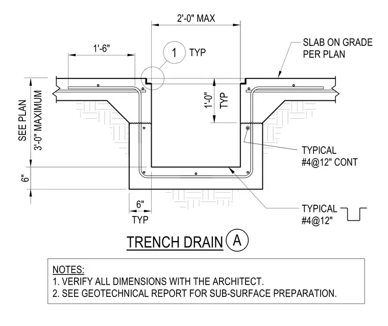
A reinforced concrete trench drain is recessed into a slab on grade per plan. The channel features a typical width of two feet maximum, a typical depth of one foot, and six inches of concrete thickness at the base and sides. Reinforcement consists of number four rebar at twelve inches spacing continuously typical throughout the trench and slab assembly. The sub-base preparation requires review of the geotechnical report, and all dimensions must be verified with the architect.
NOTES: 1. VERIFY ALL DIMENSIONS WITH THE ARCHITECT. 2. SEE GEOTECHNICAL REPORT FOR SUB-SURFACE PREPARATION. A TRENCH DRAIN 6" SEE PLAN 3'-0" MAXIMUM 6" TYP 1'-6" 2'-0" MAX TYPICAL #4@12" CONT TYPICAL #4@12" SLAB ON GRADE PER PLAN TYP 1 TYP 1'-0"
Members view this detail in full resolution, download the CAD files (SVG, PDF), and can adapt it in the built-in CAD editor — export DXF, DWG, or PDF.
Start membership