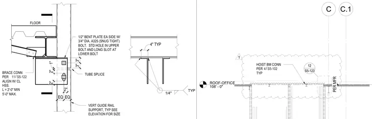
An elevator guiderail support assembly anchors to structural floor framing. One-half inch bent plates are positioned on each side of the connection, secured with three-quarter inch diameter ASTM A325 snug-tight bolts. The connection features a standard hole in the upper bolt location and a long slot at the lower bolt location to accommodate adjustment. Brace connections are aligned withircraft the centerline of the hollow structural section, maintaining a length between two and five feet. A typical tube splice and hoist beam connection per manufacturer instructions complete the surrounding structural interface.
VERT GUIDE RAIL SUPPORT, TYP SEE ELEVATION FOR SIZE 1/4" TYP FLOOR 1/2" BENT PLATE EA SIDE W/ 3/4" DIA. A325 (SNUG TIGHT) BOLT. STD HOLE IN UPPER BOLT AND LONG SLOT AT LOWER BOLT 2" 4" TYP BRACE CONN PER ALIGN W/ CL HSS. L = 2'-0" MIN 5'-0" MAX. / 11 S5-122 2" EQ EQ 3" 3" TUBE SPLICE 1" 2" C.1 ROOF-OFFICE 108' - 0" C PER MFR HOIST BM CONN PER TYP / 4 S5-102 1 S5-123 12
Members view this detail in full resolution, download the CAD files (SVG, PDF), and can adapt it in the built-in CAD editor — export DXF, DWG, or PDF.
Start membership